
Here is a method you can use to help reduce the errors (not completely remove, that can't be done) you create in your drawings.

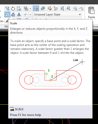 |
| The Scale Command's Tool Tip |

 Ok I won't win any awards for this, but perhaps in the hands of a creative artist something great could be drawn.
 You also have control of what type of units you are using in the drawing as well as the page size. You have two choices, imperial (inches) or metric (millimeters). If you draw a shape in inches but now want to switch to millimeters, go ahead. Project Draw automatically knows the difference. A five inch object will automatically convert to 127 millimeters, for example. I mentioned earlier that there are different sheet sizes to choose from. When working in imperial units, you can choose from ANSI or ARCH A, B, and C sizes. They also have legal, 8"x10" and 30"x 42". If you don't like those settings, enter in your own, like 24"x36". The metric units have ISO A2, A3, A4, and A5. But again, you can still enter in your own size in millimeters.
Many times in AutoCAD, users will enter an angle in Degrees. Maybe even in Degree/Minutes/Seconds. If you are a surveyor or are working with a survey drawing, you will see angles (or bearings) written something like this:
N45d20'6"E (where d is the degree symbol)
This means the angle is North 45 degrees, 20 minutes, 6 seconds, East.
Users can input angles just like this if we need to. When drawing a line, pick your first point, then type in: Make sure to start with the '@' symbol. Then enter the distance, (here it is 200) then the less than sign (I would type it in but my blog thinks I am trying to type in an HTML tag!!) then N (for north or S for South) the angle number (45) d to let AutoCAD know it is the degree, then the minutes and seconds if any. Don't forget to type in the symbols ' for minutes and " for seconds. Finish up with your last direction e (E for east and W for west.)
CADsmart really excels in the larger firms and for assessing interviewees. It doesn’t perform as well with small firms that have four or five CAD techs. If you are managing only five CAD users, then you already know where they struggle and where they excel. But if you have twenty, fifty, a hundred, or more, then you don’t have the time to know them as well. That’s where CADsmart can help. I also like it when assessing interviewees. It provides a fair environment for the tester, which gives you a more accurate assessment. Many firms have customized their CAD environment and that can intimidate and overwhelm a candidate if they are trying to get a job by taking a test in a place they are unfamiliar with. Sometimes upper management doesn’t understand these types of situations. CADsmart is a fairer assessment process.
Now that we have assessment data on our CAD users, how do we get to it and what do we do with it? Access is easy enough. Go to CADsmart’s website and log in. You will need an account to be able to do this. We will talk about getting an account later on. When you log on there are several options available to you. You can go directly to the performance charts, or go to the assessment results.
The performance charts provide a quick visual guide to the information collected. You can see your scores sorted by group (employee, interviewee, etc.) The charts provide you with a performance spread in one graph and a stage performance in a second graph. This gives you an overall look and a more detailed comparison. There are different color codes to help you differentiate between the groups and the benchmark. Hopefully the benchmark is the lowest set of scores you have! Everything here is online, but you can get the data and print it, transfer it to a PDF, or export it to a spreadsheet. There are many ways to see the data and to get it to use for yourself.
The assessment results tab is where you can go to get more detailed information about the individual test results. You can sort the data by any column and in any order. You can sort it and then resort it by clicking on the headers. You can add and sort your users results by groups. The default groups are Employees and Interviewees. In my test I added groups for our departments; engineering and surveying. This is a nice feature if you need to manage the results from different offices or departments.
The assessment results tab lists each user by name. If you click on the users surname it will open up a window that provides the basic testing data (time, date, CAD platform) and recommendations for training based on the assessment results. If you click on the result score, another window opens up providing a more detailed analysis of each stage. It provides the end score, the time taken, and an analysis. The analysis lets you know what the candidate did incorrectly! This is a great feature because it can better explain to you why they scored the way they did. How useful is an assessment that just says, “You scored an 85%.”? Not very. At the end of the assessment results it compares the score and time with the benchmark letting you know how your skills compare. When you are finished, you can click the print button to print out the certificate (that’s what they call the data sheet.) I was disappointed that CADsmart didn’t provide other output devices as in the Performance Chart Tab like the PDF and Spreadsheet options. That’s how you look at and use the assessment data. It’s very simple to use.
There are other tabs too that you would expect; account details (name, address, password, etc.), resources (this is where you download the assessment software and instruction guides), software settings (turn off testing options like the clock, intro movie, welcome message, and extra candidate labels), booking system (where you can schedule assessment times), support (where to go if you need help), and logout (that one’s obvious!)
You can see that with CADsmart, managers have many tools available to them to better assess the CAD skills of their users. There are many resources to go to for help (like the managers’ video) and more instruction. CADsmart also has some customization features that might help you out too. Overall I feel that CADsmart is a good program and a great service. It is easily used and implemented.
The biggest question is; how much does it cost? CADsmart has two methods, the Premier and the Classic. The premier provides unlimited use and with all the assessment data, recommendations, the whole thing. The Classic level of subscription only provides unlimited use of the Assessment Software and access to your data. This might be enough for some managers. It will depend on you, your needs and your budget.
The pricing varies from the classic to the premier and by the number of users. It seems to me that they are looking for a general usage amount. The website states that you can assess your users as many times as you want including as many interviewees as you have.
The price difference on 1 to 15 users from the classic to the premier was only about $300 (U.S.), ranging from about $1500 to about $1800 per annum. The price on 100 users ranged from about $6300 to about $7500 per annum. You will need to check for yourself as prices may change. They also provide pricing for other countries. The more users you add the higher the price.
Depending on the amount of employees you have, the price will obviously vary. If you have about 100 users, then the cost will be about the same as one license of your CAD software! I think that is a good price and well worth the money spent. I feel that CADsmart is a good investment in your company.
A few days ago I gave you a brief overview of a software program I found called CADsmart. It is a program that you can download and run within AutoCAD (or Microstation) in order to assess your users’ general CAD skills. It doesn’t test programming skills, nor is it release specific, it only looks at general CAD drafting skills. Knowing what areas your users excel in along with the areas they don’t is very useful. It allows you to train them properly and where they need it.
Last time I gave an overview of what CADsmart can do, generally speaking. Now I want to get more specific.
Before you get started using it and before your users test with it, I recommend that everyone involved watches their online videos which let everyone know what to expect and how it works. This is a nice touch. It helps to relieve some of the stress that people have when they are being assessed, especially if they are taking it as part of a job interview or as a personnel review as an employee. People get nervous and they might not perform as well as they normally do when under pressure, so this feature helps.
Another feature that helps the scores be more accurate is that CADsmart runs within AutoCAD (or Microstation). It would be nice if you didn’t have to have AutoCAD to take the review, but this method does have a nice bonus to it. Since the user (if he/she is a current employee) is taking the assessment in a CAD setting that they are familiar with, they will perform better. They perform better because they are being tested in the same environment that they work in everyday. CADsmart also gives the user the ability to arrange the toolbars, pallets, icons, etc. to their liking before the exercise begins. This also helps interviewees test better in a new and different setting. Everyone involved gets better and more accurate scores.
Ten exercises are taken, each one covering different aspects. These ten topics are: Lines, Sheet Set Up/Xrefs, Circles & Arcs, Text, Blocks/Cells, Dimensions, Layers/Levels, Preferences, UCS/ACS. As you can see, these topics cover the general skills needed to be able to work with CAD software. It also breaks them up enough so that we can see what areas we do well in and in what areas need more training.
In order to take the assessment, the CADsmart software must be downloaded and installed on the testing machine. Once it is installed, log on and begin. If the candidate hasn’t watched the introduction movie yet, they will get the option during the set up phase. Some information about the user will have to be filled out in a form. This helps CADsmart identify who you are. They provide a guarantee that says they won’t give out that information to any third party; only CADsmart, you and your company will have access to that data. Once the form is filled out they can begin the assessment.
Each exercise will provide instructions and a preview of what is to be done. It is up to the candidate to figure out what to do and then do it. Be careful when reading the instructions, just as the video says, because if you don’t follow the instructions and do as you are told, your score will be lower than it could be! Once done, the candidate will receive an e-mail where they can go and find out their score. They will also receive an assessment comparing their score to the benchmark as well as recommendations on what areas to improve. This is one of the reasons they had to fill out all of that personal information, so that CADsmart would know who they are.
CADsmart is a simple to use program that provides valuable CAD skill assessment data and comparison. It is easy for users to test with and easy to set up. It is run in a CAD environment that is familiar to the candidate thus giving more accurate scores and skill assessments.
I’m going to stop again so that our minds won’t melt. In the near future I plan on taking a closer look as to what CADsmart offers the manager. We will look at the tools it provides in skill assessment, charts, data management, the benchmark, how to access the data, etc. We’ll also take a look at what managers can do with the information they just collected.
Happy CADDING
CAD-a-Blog is about teaching CAD skills, especially AutoCAD skills. With that in mind, I try to keep my eyes open for products or services that can help users (and me too!) better themselves. I feel that I have found such a product.
Consider this scenario; imagine that you need to hire a new CAD user for your company. How do you know if that user can in fact use CAD? How do you know the extent of his or her skills?
Also consider this; how can you measure the CAD skills of your current users?
Well I have come across a product that comes from the United Kingdom. It is from CADsmart.
CADsmart is a company that provides testing software that measures general AutoCAD (and Microstation) skills in users. It has the ability to measure CAD drafting skills, not programming, not customizations, but CAD skills. In a nutshell, the user takes a series of drafting based assessments, each one covering a specific topic. The results are compared to a benchmark that has been developed by CADsmart from thousands of users that have taken the same or similar assessments. The user is scored individually and in comparison to other users. For example, one segments score could state that you scored an 80%. That means that you were 80% correct. Now compare that score to the benchmark and you will have a means to measure your abilities relative to the thousands of users that have already taken the assessment. This software gives you a score for the user and tells you if it is a good score or not.
CADsmart’s benchmark is meant to represent the average user. If you score above that, then you should be a good CAD user. If you score below the benchmark, then there might be some areas for training. The assessments are scored separately on overall accuracy and time taken. These two measurements can be compared to the benchmark or to other employees in your company.
CADsmart’s assessments cover specific topics. Each one consists of a series of steps that the user must complete. It doesn’t matter how the user gets the work done, or how long it takes, only that the end results are what they need to be. This is one of the main reasons that I like this software because every user will work in a slightly different way and what matters is the final drawing, not so much as how it was drawn. I said that time doesn’t matter, well it doesn’t affect the accuracy score, but it is measured and compared to the benchmark. So keep it in mind that you need to be both accurate and quick, just like in real life!
Each category has its own benchmark that you can compare your score with. This is very useful because it provides a means of determining where your specific problems are. This feature is great for managers too because it enables them to find specific problem areas in their users so that they can concentrate their training programs exactly where they are needed. Time and resources are not wasted training the wrong people in the wrong skill sets.
CADsmart is not perfect. It is not cost productive for a single user to buy the software and use it on themselves, though this can be done. It works best in a group environment. You also have to have AutoCAD software on your machine in order to run it. One other thing that I understand, but didn’t like too much, is that while taking the test, I can’t pause it in case my attention is needed elsewhere (That happened to me while I was taking the test. I got a low score in the dimension portion because of it-maybe I’m just bitter!) Playing devil’s advocate, if I could pause the assessment, then I could stop it, figure out the task, then start again. That’s cheating, so I understand the reason behind it, but I want it anyway!!
That’s the gist of it. I don’t want to overload you with information, so I am going to write about CADsmart in smaller bite size parts like this. Check out their website, read about them, and let me know what you think. Later I’m going to get more into the workings of it, what it has to offer managers in terms of assessment tools, charts, and recommendations. CADsmart will test the user, show the assessment data, and provide recommendations on what areas to train the specific users in. It is a very helpful tool in my opinion.
Happy CADDING!
You can start the command by typing in MLEADER. Or, in AutoCAD 2008 go to the Multileader toolbar, and click the mleader icon. OR, go to the DIMENSION pull down menu, and then click the Multileader button. In AutoCAD 2009 you can do the same as above, or in the Ribbon, go to the HOME tab, in the ANNOTATION Panel click the Mleader icon. OR in the ribbon, go to the ANNOTATION tab and then go to the Multileader Panel. Quick tip, don’t type in ML (I know, it seems logical) because that is the shortcut for Multi-Lines. Instead, type in MLD to create a new multileader. Here are some other out of the box keyboard shortcuts for multileaders:
MLA, *MLEADERALIGN
MLC, *MLEADERCOLLECT
MLD, *MLEADER
MLE, *MLEADEREDIT
MLS, *MLEADERSTYLE
Now that we know where to go to start the command, let’s start the command. You will quickly find the multileaders work and act in a very similar fashion to leaders. You pick the point where you want your arrow head to point to (get the point yet?) and then you pick the point where you want your landing (the landing is the horizontal tail that comes from the end of the leader and stops just short of the text.) Then enter your text. Easy enough.
Now, if you want to add a second leader to this callout, then click the ADD LEADER button. Then follow the prompts. Select the multileader you want to add to. A new leader is drawn and follows your crosshairs around until you designate where you want your new leader’s arrow head to point to. It will keep doing this until you hit the ENTER key. So you can add more than one leader to your multileader at a time. It can be fun. Go crazy, get a little wild, and add tons of leaders. Ok stop, that’s too many!!
How do you remove a leader? Good question. Go to your toolbar, pulldown, ribbon panel, whatever, and click the, any guesses, REMOVE Leader button. Select the multileader you want to edit, and then select the leader you want to remove. You can keep doing this until there are no leaders left to select. If you select them all, then the multileader will be deleted, oops!! When you select the ones you want to remove, they will be highlighted. Press enter to remove them. There you go.
Now that you have multileaders in your drawing, you need to edit them, move them, and adjust them. Go ahead. Use the grip edits to do this. You can move the arrow head around just like any other leader. Look at the image provided. I have selected the multileader. See the grips that are available? The grip at the top of the text will allow you to move just the text, while the arrow head stays in place, just like regular leaders that are associated. The grip at the end of the landing, just before the text, will stretch the landing and move the text, keeping the distance from the landing to the text the same. The grip where the leader and landing meet will stretch the leader and the landing while leaving the text and the arrow head in place. Cool huh? The grip in the middle of the landing will move it and the text around leaving the arrowhead in place.
To edit the text, just double-click it and it works just like mtext. If you change the text justification, the multileader landing will stay relative to the rest of the text. If you want to change the landing position to the text, select the multileader, open the properties palette, and change the left/right attachment setting. You can set it to line up at the top, middle, bottom, etc.
There is a lot more you can do with multileaders, but that will have to come in a different post. These abilities are what really set multileaders apart from leaders. You can align them, combine them, and use blocks, standard and custom, for your callouts. We will look at those later.
Happy CADDING.
Click the Clean Screen button in the lower right hand corner of the screen (it looks like a box) to toggle it on and off. OR, press “CTRL+O” (that’s the letter “O” not the number zero).
Happy CADDING
Click on the COLORS button near the center on the left of the window. A new dialog box will come up. At the TOP on the LEFT, there will be a box called Content. Select (it will highlight when you select it) the 2D MODEL SPACE option. Then near the center of the window, on the interface element OPTIONS, select the UNIFORM BACKGORUND option. Then, on the top right of the screen, there will be a COLOR option box. Click on the arrow to bring up a list of colors. Pick the one you want (I chose black).
That is how you switch your colors, for anything. Play with the options and see if you can come up with a better color solution.
Happy CADDING