Tuesday, August 12, 2014

Lenovo announces the Thinkstation P-Series

Lenovo has announced the reworking of its P-Series line of workstations. The design has been reworked from the ground up.  Lenovo says they have focused on Ease of Use, Thermal Management, Flexibility, and Performance when updating the P Series.  In May of 2014 Lenovo announced the entry-level P300 workstation. Today they add the P500, P700 and P900 to that model.  The P-Series workstation is designed for professionals in engineering, architecture, media & entertainment, oil & gas, medical & science, finance and other industries that need a powerful computer on a daily basis.

The Lenovo P-Series has been completely redesigned with a focus on performance through temperature control and ease of use. The chassis is completely tool-less and can be completely broken down in a matter of minutes (Lenovo makes this claim on their website and videos). That’s a big deal when maintenance is required especially when your IT department has multiple workstations to maintain.

Monday, June 16, 2014

My AutoCAD 2015 and AutoCAD LT 2015 Training Videos Now Available

Just released our my newest set of training videos covering AutoCAD 2015 and AutoCAD LT 2015.  Each video is 10.25 hours long and covers the basics of each program.

Learning Autodesk AutoCAD 2015 Training Video
A Practical AutoCAD Training Course That Teaches Real World Skills

In this project-based Learning Autodesk AutoCAD 2015 video tutorial series, you'll quickly have relevant skills for real-world applications.

Follow along with our expert instructor in this training course to get:

  • Concise, informative and broadcast-quality Learning Autodesk AutoCAD 2015 training videos delivered to your desktop
  • The ability to learn at your own pace with our intuitive, easy-to-use interface
  • A quick grasp of even the most complex Learning Autodesk AutoCAD 2015 subjects because they're broken into simple, easy to follow tutorial videos
  • Practical working files further enhance the learning process and provide a degree of retention that is unmatched by any other form of Learning Autodesk AutoCAD 2015 tutorial, online or offline... so you'll know the exact steps for your own projects.


Learning Autodesk AutoCAD LT 2015 Training Video
A Practical AutoCAD LT Training Course That Teaches Real World Skills

In this project-based Learning Autodesk AutoCAD LT 2015 video tutorial series, you'll quickly have relevant skills for real-world applications.

Follow along with our expert instructor in this training course to get:

  • Concise, informative and broadcast-quality Learning Autodesk AutoCAD LT 2015 training videos delivered to your desktop
  • The ability to learn at your own pace with our intuitive, easy-to-use interface
  • A quick grasp of even the most complex Learning Autodesk AutoCAD LT 2015 subjects because they're broken into simple, easy to follow tutorial videos
  • Practical working files further enhance the learning process and provide a degree of retention that is unmatched by any other form of Learning Autodesk AutoCAD LT 2015 tutorial, online or offline... so you'll know the exact steps for your own projects.


Each Training video comes with working CAD files.  I introduce the user interface to you and show you have to navigate within your drawing files. At the end of most sections is a “Chapter Project” that focuses on the skills you just learned.  Several of those projects build on top of the other culminating in a final project where you will create drawings for a small movie house.

Check out the individual websites for more information and pricing.

AutoCAD 2015
AutoCAD LT 2015

Tuesday, May 27, 2014

Autodesk AutoCAD Shortcut Guide

Autodesk has put together a robust guide of shortcuts for AutoCAD users. This guide is an eleven page PDF listing function keys, keyboard shortcuts, command aliases, and toggles, hot-keys, and a page of printable keyboard stickers.

Friday, March 28, 2014

An Overview of the Features, Tools, and Changes in AutoCAD 2015


Autodesk has released their latest version of AutoCAD as AutoCAD 2015. I have been beta testing it for several months now and am very happy to start talking to you about it. I would like to start off by saying that there really isn't anything new in this release. Autodesk did not add any real new tools to their flagship product. At first first I was disappointed; a knee jerk reaction I believe. After using it for a while now (but not in a production environment of course) I have come to find that what they did change makes AutoCAD 2015 one of the my favorite "updates" to the AutoCAD line in a very long time. Don't get me wrong; I love new tools as much as the next person. But do you know what I love even more than new tools? Increased efficiency! Improved workflow! A smoother working user interface. Tools that actually provide something useful.

Their are some "new" things but in reality, most of them are just the same things we had before but in a different way or look. I also like it when Autodesk removes tools that I never used. In some cases Autodesk has removed some of the bloat and replaced it with a tool that I can actually use and will use. I speaking of Quick View Drawings and Layouts. they were slow, awkward, and I never ever used them. they are gone! In AutoCAD 2014 Autodesk added Bing Maps for project location.  Great idea but we couldn't do anything with those maps. Now we can! We can actually embed and print the maps now! Why was that so hard? the user interface got an overhaul. Nothing major, just some simple changes that actually make a huge difference. One thing many of you might not like is the removal of the Classic Custom Interface. Many of us used it as a very quick way to turn our toolbars back on. It's gone. You can still access all of the toolbars and menubar; those items did not go away. Linesmoothing is one of those "little" things that actually make a big difference.  Between that and the new darker color scheme I found it easier to stare at my screen all day. The Welcome screen is replaced with the New Tab, text bullets are now automatic, there is a new lasso selection tool, we now have cross-hair badges, and ribbon Galleries.  You can now collaborate with Design Feed within your company without uploading to Autodesk 360 exclusively and model space viewports are extremely easy to work with. Let's take a closer look shall we?

UI and Visual Changes


The First Thing You Might Not Notice is What’s Missing.


One of the first things that has been changed is something that is no longer there.  The Welcome screen is no longer available!  You know, that screen that pops up the first time you start AutoCAD and promptly set to never turn on again.  In its place is the NEW TAB.  The New Tab displays when you launch AutoCAD, have no files open or start a new tab.  The New Tab is made up of two content areas; Learn and Create.  Each content area provides access to different tools.


New Tab: Create


The Create page has three main columns; Get Started, Recent Documents, and Get Connected.  These categories are fairly obvious as to what they do or contain.  When a New Tab is created you will be brought to the Create Page by default.  The Get Started column provides tools for starting a new file, open an existing file, access your templates, and can take you to sample files.  The Recent Documents lists your most recently opened files and the Get Connected column provides a place to log onto your Autodesk 360 account or to create a new account if you don’t have one.

New Tab: Learn


The Learn page of the New Tab provides users access to the “What’s New” videos, the “Getting Started” videos, tips and Online Resources.

UI Color Changes


AutoCAD 2015 has a new color theme.  It is said to be a “modern dark-theme”.  These color changes include the ribbon, status bar, and pallets.  It does minimalize the contrast between the drawing space and the tools around the workspace.  This color change hopes to lessen the strain on a user’s eyes.  You can change this color scheme in the Display tab in the Options dialog.

The Workspace Dropdown is turned off by default in the Quick Access Toolbar.  It is still there and can be turned back on.  Also note that the “Classic” workspace has been removed.  If you want a more “classic” look to your user interface you will have to manually set it up.

The ribbon tab VIEW has been altered to include tools that control the visibility of several User Interface elements.  There you can find controls for the UCS Icon, ViewCube, Navigation Bar, and Layout Tabs.  There is also a new BIM 360 Ribbon Tab that provides quick and easy access to your BIM 360 Glue account.

Layout tabs now have a Plus sign (+) button to aide in the creation of new paper space tabs.  You can always right-click the tabs to gain access to several new layout tabs creation tools.  If you have so many tabs that they can’t be shown there is a new overflow menu that will list the remaining tabs in a column.  There are new color controls for layout tabs in the Display tab of the Options Dialog.

Improved Graphics During and After Object Creation


There is a variable called LINESMOOTHING that allows users to toggle on/off anti-aliasing in viewports when the 2D wireframe visual style is active.  This does not affect printing only on the screen visual display of 2D objects such as lines, arcs, circles and drawing aids (like grid lines).  These controls are found in the Graphics Performance dialog box.

The new system variable COMPLEXLTPREVIEW provides controls for more visual feedback when creating and editing objects.  For example; the move command will display the selected objects in their original position but with a faded deletion effect.  Also, complex line types are displayed as you draw them, move, copy or rotate them.  AutoCAD 2015 will also display the color, linetype, and lineweight of lines and polylines as you draw them.

AutoCAD 2015 provides visual feedback when you preselect and select objects in a few ways.  When your cursor hovers over an object the geometry will appear thicker and either darker or lighter depending on the color of your background.  If you have hardware acceleration turned on and you select an object, that object will remain highlighted (thicker and darker/lighter) and its color will change to make identifying it visually easier.  The Trim, Extend, Lengthen, Match Properties, and Break tools now all have command preview functionality.

AutoCAD 2015 has a new selection tool called Lasso Selection.  To start a Lasso Selection click your cursor in a blank area of the drawing area and drag the cursor around an object/objects.  The “old fashion” window and crossing window selections are still available, simply click in a blank area and release the mouse button.  Click and Hold the mouse button to start a lasso selection.  This selection tool’s availability can be turned on or off in the Selection Tab of the Options dialog.

Crosshair Badges


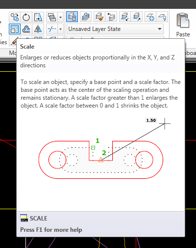
The AutoCAD 2015 cursor has had a few changes to it.  The crosshairs have been removed from within the pick-box area to help you see what you are selecting.   Autodesk has added Badges to the crosshairs.  These new badges will appear on your crosshairs relevant to specific commands.  Most of them look similar to the command icon they represent.  There are badges for making a Selection, Copy, Move, Scale, Zoom, Erase/Delete, Rotate and several “inspection” tools such as Distance, Radius, Angle, Area, Volume, List and ID.  The inspection badge looks like a question mark.  The Rotation badge looks like the rotate icon and also indicates the angle of rotation (this will be a nice visual queue).

Ribbon Galleries


There is a new tool to help when inserting blocks that are already in the current file.  When you use the INSERT command from the Ribbon and there are already blocks in the file, a panel window pops up below providing a visual representation of the blocks that are available.  There are also galleries for styles including dimensions, multi-leaders, text, tables, and table cells.

Model Space Viewport Controls


Model Space Viewports are now much easier to control.  Create a few model space viewports as you normally would (use the command viewports).  The active viewport has a very visible blue border around it.  Click and drag the edges of any viewport to move its border.  This allows for very quick changes to the size of the viewport.  Along the viewport borders you will see a Plus (+) sign as shown in the figure below.  Click and drag this icon to split a view port creating a new viewport.  Drag the cursor left/right or up/down will split the viewport horizontally or vertically.  You can also press and hold the CTRL key while dragging the cursor on the viewport border to split it.  Drag a border to one side to collapse it, joining the two viewports together.


The status bar now has a new tool that allows for Isometric environmental controls.  It provides one-click access to turn on an isometric drafting state and to change isoplane settings.  Click on the iso options and a flyout will appear providing a new menu where you can choose between Isoplane Left, Isoplane Top, or Isoplane Right.  Click the icon to toggle the setting on or off,  Click the arrow to access the flyout controls.

Multi-line Text Enhancements


AutoCAD 2015 has several small enhancements to the way multi-line text works.  Some of these enhancements are new while others make existing functionality a little bit better.  If you have hardware acceleration turned on then the mtext editor will be see-through.

Text Editor Enhancements


Meaning that if there is geometry behind the editor you will be able to see it.  This is nice if you are annotating your linework and want to be able to see how your text will look around the linework.  Columns now have a corner resizer allowing you to resize their width and height more easily.  Pass the cursor over the bottom or right edge of the editor then you can change either just the height or just the width accordingly.  Autostacking now produces a clickable icon that gives you instant controls of how your stacked text will be displayed.  Paragraph tabs in the editor now have tooltips making controlling and setting them much easier than before.  The text editor has a match properties button so that you can match properties inside a text object.  The new TEXTALIGN command will enable quick alignment of text objects.  Start the command, select the text objects you want to align (single line, multi line, or attributed text), then select the text object you want to align them with.  You can also select two pints creating a line to align with.  There are also spacing controls available.

Auto Bulleting


AutoCAD mtext now has auto bullets and numbering.  If you have to create numbered lists or notes on a regular basis this will be a nice feature.  Of course this feature can be turned off or on.  Open the mtext editor (edit some text to do this) go to the Bullets and Numbering panel on the Mtext Editor contextual ribbon that appears and click the arrow.  Click to turn off the “Allow Auto Bullets and Numbering” option.  It will have a check next to it if it is on.  To use this feature type a number or letter that you will use for your bullet.  You can also use a symbol.  Then follow it with one of these characters:

  • .
  • )
  • >
  • }
  • ,
  • ]


Follow those characters with either a space or a tab and the auto bullets will begin.  If the auto bullet feature is activated a symbol icon will appear.  That icon is clickable and will provide further controls for the bullets.


Caps Lock


AutoCAD mtext has had an all caps or all lower caps setting for a while now.  Now there is also an Autocorrect cAPS Lock feature.  It is on by default but you can turn it off by right-clicking within the text editor and clicking the option.  This new feature works when you press the SHIFT key to type the first letter of a word and then release the SHIFT key for the remainder of the text that you type in.  AutoCAD will autocorrect the capitalization by capitalizing the first letter and changing the remaining letters to lower case and then turn off the caps lock.  This feature will work wherever there is text as in tables, leaders and dimensions.


Geographic Location and Maps


AutoCAD 2015 has greatly improved on the Geographic Location tools and maps.  Setting your file location has been streamlined.  Don’t forget, to use the maps you must be logged in to your Autodesk 360 account.  Otherwise you can only set your location via latitude and longitude coordinates.  When you have set your location and coordinate system you can display an aerial map.  The resolution of the map changes as you zoom in and out trying to balance image quality and computer performance.  Now you can actually use the map shown in your drawing.  Before all you could do with the map was see it while you were working in AutoCAD.  Now you can capture the map for printing.  The map is then embedded into the drawing, increasing the file size of course but this means the map goes with your file.  The map image is grip editable so you can move it, resize it, and rotate it just like any other image.  Also note that there are three versions of the map; road, aerial, or hybrid.  Even if you embed a map image you can always change the map type later on.  Slidebars on the Map Image ribbon tab let you change the brightness, contrast, and fading of the map image.  The map image is only updated if you choose to reload the image, otherwise it stays as it was inserted.

Autodesk ReCap and Reality Capture


How AutoCAD uses point clouds is a bit different now.  All of the hard work is done in Autodesk ReCap.  AutoCAD no longer supports PCG and ISD files nor can it create them.  Now AutoCAD uses ReCap point cloud files or RCP and RCS files.  ReCap can handle PCG and ISD files as well as a long list of other point cloud file types.  Process the data in ReCap (which comes free with AutoCAD), create an RCP or RCS file and use that in AutoCAD.  Once you have attached a ReCap file to AutoCAD you have many more visual controls available than before, even geographic location.  You can control point size, level of detail, maximum number of points per file, colorization, color mapping, lighting tools, and you can crop the points to display a specific area.  There is also a new Point Cloud manager that allows for multiple point cloud files to be attached to your file.  There is now also a Point Cloud Object Snap control that allows you to “snap” to point cloud data.  The 3D Orbit command now allows you to snap to a Cloud Point and use it as the focus of your orbit.

Changes to Design Feed


Design Feed is a collaboration tool built into AutoCAD.  This release of AutoCAD streamlines the way Design Feed works.  One of the complaints of Design Feed was that the file had to be uploaded to an Autodesk 360 account to able to use the tool.  Now users can save the file only to their company’s server and still use Design Feed.  Note that only users that have access to the company server can access the design feed data.  This should be fine if you are only collaborating with coworkers.  To share Design Feed data without third parties you will still have to upload the file to Autodesk 360.  Now when you etransmit files with Design Feed data you can opt to have that information removed when creating the etransmit files.

Miscellaneous Changes


Changes to Help


AutoCAD’s Help has a new feature called Find.  This new feature will help you find the command in the Ribbon.  While Help is open and if the command is presently visible in the current Ribbon nothing will be displayed.  If the command is not visible then a link that says FIND will be visible next to the command listing in the help window.  Click this link and an animated arrow (see the figure below) will appear pointing you to the tool.  If the tool is not accessible from your current workspace or is in a hidden or contextual ribbon tab or panel, a tooltip will appear providing instructions on where to find the command.
Figure 11: Help can “help” you find your commands.

The Little Things


It is now possible to filet arc segments that are polylines.  When creating a polyline arc you can press the CTRL key to draw the arc in the opposite direction.
When creating dimensions, AutoCAD 2015 will now ignore existing dimension extensions lines to keep you from accidently snapping to them instead of the object you want to dimension.  You can turn this on or off in the Drafting Tab of the Options dialog.  Also when you create a continuous baseline dimension (with the DIMCONTINUEMODE system variable set to 1) your new dimension will inherit the style of the dimensions you are continuing from.

AutoCAD now uses Autodesk’s new ATF (Autodesk Translation Framework) to import model data from other file formats.  It supports importing meshes, curves, object colors and layers.  Now you can also purge orphaned DGN data.  Thank you Autodesk for that.

The Autodesk BIM 360 Add-in is now included as an option to install with AutoCAD.
You can configure AutoCAD for either hardware or software display rendering modeling to take advantage of the new Performance and Visual tuner tools.

PNG (Portable Network Graphics) files are now supported for button image use.
The Application Manager is integrated into AutoCAD 2015.  From it you can access and manage your installed Autodesk Applications.

AutoCAD 2015 provides new tools to help you analyze and troubleshoot performance problems with your hardware.


Thursday, March 27, 2014

Review HP Z1 All-in-One Workstation

I had a chance to take a look at Hewlett Packard’s all-in-one workstation the HP Z1.  Here is what I found.

Overview

The HP Z1 was a great machine to use.  I loved that it was compact but yet big enough. It was easy to transport and it performed as well as any other workstation.  With all of its components being literally in your face I expected the noise to be a bother. I found that it wasn’t. The HP Z1 runs very quietly and noise was not an issue. It had plenty of ports and functioned just like any other workstation. Not having to bend under my desk to insert media was a nice little benefit that I wanted to make sure I mentioned. Opening the body of the machine was quite easy to do and all components are easily accessed. The lack of wires was also very nice.

Main Specs


  • 27” Monitor
  • Intel Xeon Processor
  • 16 GB DDR3-1600 ECC RAM
  • Nvidia Quadro 4000M GPU
  • 1 TB SATA Hard Drive
  • Windows 7 Pro Operating System
  • HP SATA Blu-Ray Writer Slot Load Optical Drive
  • 400W Power Supply
  • ISV Certification
  • Tool-less Design Chassis
  • Dual Display Capable


Tuesday, March 25, 2014

BRACE YOURSELVES - AUTODESK 2015 PRODUCTS ARE COMING!!


That means so are the "What's New" posts and articles.

Stay tuned!

CAD Standards Should be Vague

It is fairly standard these days for a company to have a CAD Standard. The point to a company CAD Standard is to ensure production quality and to maintain an efficient work flow. It keeps all construction documents in line and makes certain that everyone can work with everyone else’s files. If your CAD Standard fails at any of these items then it is failing you.

One key aspect to help ensure a CAD Standard works properly is to keep many of its aspects vague.  Locking down criteria to something exact can stifle production and increase bloat. Definition and specifics are great but they can create bottlenecks in your production process. If your template CAD file has several thousand layers (as an example) but yet you find you never have the right layer, then there is an issue that needs to be resolved.

Friday, March 21, 2014

Orange Juice Studios Kickstarts Mobile CAD Project CADO

Orange Juice Studios is trying to create a fully mobile CAD program.  They are calling it CADO.  CADO is planned to be a full 2D mobile CAD program running on iOS and the iPad. It will be compatible with DWG and DXF files and have a full set of drafting tools.  This project has been in development for about two years and the developers are looking to finish things up.  They are hoping to raise £50,000 by Wednesday, April 2nd, 2014 through Kickstarter.  This Kickstarter round is to help raise some capitol and to help gauge the interest in the program.  I spoke with the developers and was able to get an idea of what they want to accomplish with CADO and their plans for the future.


Thursday, March 20, 2014

5 Ways 3D Visualization is Building the Future

3D visualization and 3D design have come a long way from flat, cartoonish looking images. Today’s Computer-Aided Design (CAD) software offers realistic models of, well, pretty much anything you can dream up. From altering the course of a freeway to designing medical instruments (and printing them out to exact specifications), the world of 3D visualization has discovered a new level of usability – one that seemed unreachable only a few decades ago.

Challenges resulting from today’s massive design projects are met by utilizing CAD software, along with experts in the field. Together, they craft the places we will one day live and the transportation we will use to get around. Here are 5 industries turning to 3D to pave our road ahead.

The Next Generation of Construction: Taking existing structures and using AutoCAD design suites to figure out if additions will be supported by the foundation, is one way architects are restoring the face of urban areas, without completely destroying the current buildings. Three-dimensional applications can not only assist architects develop new additions to a brownstone, but also help them figure out if a four-story expansion of a building will be structurally sound.

Monday, March 17, 2014

How to Re-size a Pipe Cross-section on an Exaggerated Scale Without Thinking

The Scale Command's Tool Tip
I had a profile view with an 18” diameter pipe drawn in cross-section that actually needed to be 24” in diameter.  I know you are thinking, just draw a new circle with a 24” diameter.  Sure, that’s what I would usually do.  In this case though our cross-section was a roadway profile and we draw those with an exaggerated Y-axis scale.  In this case the x-axis scale was at 1:40 and the y-axis was drawn at 1:4.  We do this to help visualize the changes in elevations along the y-axis.  It’s a common practice in civil engineering plan and profile roadway designs.  These types of cross-sectioned pipes are typically drawn with an ellipse.  I could have taken the time to do the math and determine who wide and tall to draw my ellipse.  I also had a pipe drawn in at 18” that was properly scaled in across both axis.  I copied it and used the scale command.  What scale did I use?  24/18.   That’s not a scale.  Sure it is and it enabled me to get this job done in seconds.  Let me explain.

I had a pipe drawn at 18” in diameter.  It was already an ellipse so it was scaled properly in both the x and y axis.  I just needed it to be a 24” diameter pipe.  In order to show an 18” diameter pipe in a 40 scale drawing at a scale factor of 4 we have to draw a 15’ diameter pipe about the y-axis that is also 18” wide across the x-axis.  This makes for a tall and skinny ellipse.  A 24” pipe would be drawn at 20’ tall.  That is because we scale the y-axis “up” to put it at a different scale in the drawing view.  This math can make your head hurt so do the easy thing.

Friday, March 14, 2014

Pi Day 2014


Today is Pi day and I love Pi Day!!  It’s a day to celebrate math and all of the wonderful things it does for us in our lives.  As a society we could not exist without math.  Everything we do requires math in some way.  You can’t live without math.

Around the globe teachers are taking advantage of Pi Day to help students in a creative way.  There are all sorts of Pi Day projects.  Here is one example that I found.  One student made a Pi song and posted it to YouTube.  It was created by MC Squared Equals E and it’s called, “Pi God”.  The lyrics are in the notes, just expand them.  Great stuff here.  Very creative.

Youtube link

Over the past year I have found a great website called QuickandDirtyTips.com.  I go there mostly for the Grammar Girl podcast which is fantastic!  But I just found the page Math Dude!  Yep.  It’s a guy that talks about math.  He has a great Pi Day post today.  Here’s the link:

http://www.quickanddirtytips.com/education/math/what-is-pi

How are you celebrating Pi Day today?  We have several pies ready to go today.  One is a Key Lime Pie the other is a Cherry Pie and I think we are going to load it up with ice cream too!!  YUM!!  Pie Day is yummy!!

The Nerdist Channel made The Pi Episode: Math Bites with Danica McKellar IT IS EPIC!!!  Check out all of the nerd cameos in it!


Also, don't forget that it is Albert Einstein's 135th birthday today to!!  you know the universe is aligned in some way when Pi Day is the same day as Albert Einstein's birth!  What are the odds?

Thursday, March 13, 2014

Announcing Autodesk Instant – Group Messaging App from Autodesk


Autodesk launches group messaging app Autodesk Instant.  Right now it is only available in North America but they did manage to release it on Android and iOS.  It is a free app that provides a free service where groups of people can communicate through their mobile device.  I don’t have a lot of information on it right now but I am working on that.

Autodesk Instant will allow users to exchange messages, share photos, video and their location.  Users can communicate with anyone in their address book or a colleague that has verified their email with the app service.

The app is free and the service is free.  So far I have tried out the app with Curt Moreno, the Kung Fu Drafter, and it was easy enough to use.  He didn’t have Instant set up yet when I started the conversation so Instant went on its backup SMS delivery system.  Essentially it seems to be using my phone’s SMS options.  I was able to send him pictures just like you would any SMS or texting app.  I also sent him a map of my location.  Now he is stalking me!

Instant allows for one on one conversations or for group conversations.  I plan on investigating this new app and service from Autodesk further and will report back as soon as I have more information.

I have several questions for Autodesk about Instant and I am sure you do too.

Scott Sheppard, Autodesk Labs, discusses Autodesk Instant in his blog.

Links to download the app:
iOS
Android


Access the Last Point Used in AutoCAD With One Keystroke

There are many instances when we draw in AutoCAD where we might want to draw to the last coordinate point we used.  This is how it works.  Draw a line from point A to point B and end the command.  Start the circle command.  For the center point type @ on the command line.  This will draw the circle’s center point at the last point we drew at which is point B on our line.  See the video clip below.


You can use the “@” symbol in any case that requires a coordinate input.  If you want to draw concentric circles draw the first circle.  Draw the second but use the “@” symbol for the center point.  It will select the center of the first circle drawn.

In my post, “How to Break a Line Like a Pro” I showed you how to use the “F” or first option in the break command to break an object at a specific point.  In Tip Number 2, I have you select the exact same point to break an object in one place.   Alexandre Serdakowski, a reader of this site and a Head Draftsman, reminded me of the last point feature of the “@” symbol and that the break command would be a great use case.  Start the break command, select the object, type F, pick your point, then for the second point type in @.  It’s much easier than selecting the same point again.
Also keep in mind that if there is no last point in a drawing yet then using the @ symbol will draw your object point at the origin (0,0).

Wednesday, March 12, 2014

How to Install AutoCAD With a Different Language

If you want to use AutoCAD in a different language it is rather simple to do.  Open AutoCAD, go to the top of the screen to the information center, and click on the expansion arrow.  That will bring up a window where you need to click on the Language Packs button.  See the figure below.


Clicking the Download Language Packs button will open your web browser and bring you to the Autodesk Knowledge base website where you can download the language pack you want.  Scroll down until you find the language you want to install and click the hyperlink to download the file.

There will be several languages to download and the list of available languages will vary depending on your specific region.  Here is a partial list from my selection options and a glimpse as to what the website will look like.

Click on the hyperlink of the language you want to download.  Make sure to pick the system type that you need.  There are 32 bit and 64 bit versions.  Match your computer’s system type.  This downloads a self-extracting .exe file that will install the language pack similarly to how AutoCAD is installed.

Once the .exe file is downloaded run the file.  This will extract the needed files to a folder on your computer and should start the install program.  If it doesn't, browse to where the files were extracted to and run the setup.exe file in the folder.
Once the installer has started click the INSTALL button on the bottom right of the screen.  The installer instructions will be in the language of the language pack, but otherwise it will exactly the same.

Click the install button, select the language pack, and click install.  Make sure all instances of AutoCAD are closed before you install the language pack.  Once the install is finished you will have a new AutoCAD launch icon available.  Now I can run AutoCAD in English or in French.

Tuesday, March 11, 2014

AutoCAD – How to Break a Line Like a Pro

AutoCAD’s Break command allows you to “break” a line, splitting it into two segments. The Break command “normal” steps are as follows:


  1. Start the Break command (type break or br on the command line)
  2. Select the object to break which also selects the start of the break area (the area that will be removed from the selected line.)
  3. Pick the Second Break point.  This will break the line (arc, circle, polyline, etc.) and remove the segment from the object.

Now for the Tip.  It’s an extra step but it gives you control of where the line is being broken.

  1. Start the Break command.  
  2. Type F on the command line.  Select exactly where you want the first break point to located.
  3. Pick your second break location.

This method makes it easier to control exactly where your line is going to be “broken”.

Tip Number Two.

  1. Start the break command and select your object to break.  
  2. Type F on the command line and pick the exact place you want to break your line.  
  3. For your second point pick the exact same place.  

This tip allows you to break an object in one place leaving the entire object visually intact, but split into two segments.  It will look as if it is still one object until you select it.

You’re welcome.

Monday, March 10, 2014

What not to do in AutoCAD – Labels in a Base File

Today’s look into “You’re doing it wrong” is about labels in base files and drawing files.

Here is a screenshot of a residential plan where a new Force Main was being tied in to an existing manhole.  I have circled the manhole label because that is what I want to discuss today.  This drawing file has two “base” files referenced into it.  One is an existing conditions file that contains the existing residential area, the existing roads, the existing water main, the existing sewer system.  The other reference drawing is the new, or proposed, line work that contains the new force main.  That’s the good part.  It’s always good to separate the new and the old in separate database.  It makes things easier to manage, revise, and to work with.

The bad part is the existing manhole label.  This information is needed of course but it is in the base file.  Labels don’t belong in the base file.  They belong in the drawing file.  Now there is nothing wrong with putting the manhole data in the file in some way; in fact, that would be a great thing to do.  Put that info as attributed info in the manhole block or put it on a non-printing layer.  Better yet, use Civil3D or some other information modeling program like Civil3D to manage the data.  What makes it worse is that the creator of the drawing file took a shortcut and used the data labels as labels for the drawing file.  It might have sounded great at the time but now somebody else has to deal with them.  It turns out that the Force main was installed but not as designed.  Field conditions weren't as indicated on the record drawings.  Oops!!  It happens.  Now we have to update the drawings to reflect the changes made.

We have new labels to add, new information to integrate into the drawings but because the labels are in the base file it is making things difficult to work with.  The work that was avoided at the beginning still has to be done now.  We will copy the labels data into the drawing file, position it so that our new labels can be seen, and freeze the labels in the drawing file.   Unfortunately another no-no happened and when the labels are frozen, so are the lot numbers, and all other labels in the base file because they are all on the same layer.
 
I hate it when a file has a billion layers, but it is a great idea to use more than one layer for your text.  Put lot numbers on their own layer and put street names on their own layer.  You get the idea.  Also keep in mind that the shortcut you use to avoid work now will likely mean you will have to do the work later on, when there is even less time and less budget.

Wednesday, January 8, 2014

What Not To Do In AutoCAD – text over a table cell

This is the first in a new series of posts titled “What Not To Do In AutoCAD” where we look at practices that should never (usually never) happen in AutoCAD because, well, you’re doing it wrong!

Here is a screenshot of a legend in a drawing.


At first glance it appears that the AutoCAD user has created a legend for their drawing using an AutoCAD Table.  Great idea.  The columns and rows are set to a standard size and will ensure that each drawing’s legend will have a uniform look.  It also ensures that the text will be lined up every time with no additional effort.  Fantastic.

Now select the text in the legend to edit it.  This is what we found:


Each text instance is not a field in the table but an individual multiline text object.  The user created text objects then aligned them perfectly on the table cells.  The left most column are center justified while the second column text objects are left justified.  The text objects would have been fine if the table wasn't
already there.  The purpose of using a table in this case is so that you don’t have to line up or size the text.  The table does that for you.

Categories

AutoDesk (110) autocad (109) AutoCAD 2009 (40) augi (40) efficient (38) news (37) drafting (33) training (33) articles (30) CADaBlog (29) AutoCAD WS (23) Update (23) quick tip (22) video (21) mobile (19) review (19) cad (16) 3D Mouse (15) 3Dconnexion (15) Impression (15) Android (14) AutoCAD 2013 (14) cadalyst (14) me (14) AutoCAD 2010 (13) text (13) off topic (12) survey (12) Apps (11) hotfix (11) tips (11) 3D (10) AU (10) AutoCAD 2011 (10) service pack (10) workstation (10) Autodesk Labs (9) CAD Manager (9) annotation (9) blocks (9) cloud (9) fun (9) inventor (9) HP (8) Review-Product (8) autocad lt (8) videos (8) AutoCAD 2014 (7) Autodesk 360 (7) CUI (7) Windows 8 (7) iOS (7) new (7) IMSI Design (6) cad standards (6) files (6) google (6) infinite skills (6) printers (6) reference (6) ribbon (6) support (6) updates (6) workaround (6) RSS (5) TurboViewer (5) Upgrade (5) data (5) email (5) fields (5) guest post (5) keyboard (5) layers (5) paper space (5) pi (5) pi day (5) quotes (5) rant (5) selection (5) standards (5) styles (5) subscription (5) tech (5) 2D (4) AutoCAD Exchange (4) AutoCAD for Mac (4) Mac (4) Mastering AutoCAD (4) SketchBook (4) TurboCAD (4) UI (4) action recorder (4) dimension (4) driver (4) fills (4) large format printing (4) leaders (4) math (4) mobile workstation (4) salary (4) sheet sets (4) Amazon (3) Apple (3) AutoCAD 2012 (3) AutoCAD 2015 (3) AutoCAD 360 (3) AutoCAD Fundamentals (3) Civil 3D (3) DVD (3) DWF (3) Fusion (3) GIS (3) Kindle Fire (3) Lenovo (3) Microsoft (3) Review-Software (3) Wiley (3) Windows Phone 8 (3) Windows RT (3) annimation (3) announcements (3) autodesk plm (3) book (3) command alias (3) contest (3) filters (3) find (3) hardware (3) history (3) iPad (3) license (3) license software (3) lisp (3) menu browser (3) properties (3) purge (3) quick view (3) saas (3) tables (3) toolbars (3) weekend rant (3) what not to CAD (3) what not to do (3) #CADaBlogDVD2013 (2) 3D Modeling (2) 3ds Max (2) AutoCAD LT 2013 (2) AutoCAD LT for Mac (2) AutoCAD MAC (2) Autodesk. (2) BIM (2) CAD Services (2) CADSpeed (2) DWG (2) DXF (2) Designjet (2) Error (2) FAIL (2) Facecast (2) Freestyle (2) Fusion for Mac (2) George Omura (2) Mac OS (2) Mountain Lion (2) Novedge (2) Recomend (2) Review-Book (2) Revit LT (2) SpaceMouse Pro (2) Sybex (2) Tablet (2) Thinkstation (2) TurboReview (2) TurboViewer X (2) What Not To Do In AutoCAD (2) What's New (2) Windows (2) array (2) as-builts (2) beta (2) blog (2) circles (2) civil (2) civil design (2) collaboration (2) color (2) command line (2) commands (2) computer (2) copy (2) design (2) design review (2) dim style (2) download (2) eBook (2) eTransmit (2) file naming (2) free (2) geek stuff (2) grid (2) hotnews (2) interview (2) jobs (2) knowledge base (2) limits (2) look back (2) mouse (2) pallets (2) pgp (2) plotting (2) posts (2) press release (2) pricing (2) purchase (2) redlines (2) reference files (2) rental plans (2) shortcuts (2) sketchup (2) status bar (2) technology preview (2) tool pallet (2) tooltips (2) tv (2) units (2) video editing (2) viewer (2) webinar (2) 123D (1) 123D Catch (1) 123D Create (1) 123D Make (1) 2014 (1) 2015 (1) 3d Printing (1) ACAD/Medre.A (1) ADR (1) AEC (1) AUGI World (1) Account (1) Adobe (1) Apps Tab (1) AutoCAD 2016 (1) AutoCAD Error (1) AutoCAD LT 2012 (1) AutoCAD LT 2014 (1) AutoCAD LT 2015 (1) AutoCAD Mechanical (1) AutoCAD Revit Suite (1) Autodesk Account (1) Autodesk BIM 360 (1) Autodesk Instant (1) Autodesk PLM 360 (1) Autodesk ReCap (1) Award (1) CADDork (1) CADO (1) CTB (1) CadMouse (1) Camtasia (1) Communication Center (1) Corel (1) DWFx (1) Dassault Systemes (1) Death Star (1) Dell (1) Design Feed (1) Design Suites (1) DesignCAD (1) DoubleCAD (1) Duratec (1) E32 (1) ESET (1) ESRI (1) EliteBook (1) Epson (1) Evernote (1) Exchange Apps (1) FTP (1) ForceEffect (1) Free Form (1) Fusion 360 (1) GIS Day (1) GeoViewer (1) Geographic Information Systems (1) Geographic Location (1) Google Chromebook Pixel (1) Google Earth (1) Google Earth Pro (1) HP Designjet T2300 eMFP (1) HP EliteBook (1) HP EliteBook 8570w (1) HP Z1 (1) Help (1) Homestyler (1) IT (1) Infocenter (1) Inforbix (1) InfraWorks (1) InfraWorks 360 Pro (1) Infrastructure Modeler (1) Instant (1) Inventor 2013 (1) Inventor 2013 SP1 (1) Inventor LT (1) JPEG 2000 (1) Kickstarter (1) Kindle (1) Language packs (1) Lawsuit (1) Lenovo Thinkstation E32 (1) LizardTech (1) MS Exchange (1) Map 3D (1) Maya (1) MrSID (1) OS (1) OS X (1) Office Suite (1) Orange Juice Studios (1) P-Series (1) PLM (1) Photoshop (1) Pixel (1) Pixlr (1) Pixlr Express (1) Pixlr-o-matic (1) Plant (1) PogoPlug (1) Point Cloud (1) Previous (1) Project Artoo (1) Project Geppetto (1) Project Snap (1) R&D (1) Red Dot Award (1) Review-Service (1) Revit (1) Revit LT 2013 (1) Rhino (1) SDK (1) SMS (1) Secureload (1) Socialcam (1) Softimage (1) Solid Edge (1) SolidWorks (1) SpaceMouse Wireless (1) SpaceNavigator (1) Star Wars (1) SureColor (1) T-Series (1) TechSmith (1) The Future (1) Thinkstation E32 (1) Touch Screen (1) Trimble (1) TurboSite (1) TurboSite Reader (1) TurboViewer Pro (1) Unreconciled Layers (1) VBA (1) VOIP (1) Vault (1) Vault 2012 (1) Vela Systems (1) Visualization (1) WebOS (1) Welcome Screen (1) Windows Vista (1) Windows XP (1) Z1 (1) acad.doc (1) acad.lsp (1) acaddoc.lsp (1) acquisition (1) advice (1) aerial (1) all-in-one (1) angles (1) archive (1) arcs (1) author (1) autocad 2012. autocad lt 2012 (1) autocad. autocad for mac (1) autodesk logo (1) background (1) break (1) burrito (1) business (1) celebrate (1) check (1) checklist (1) chrome (1) chrome os (1) chromebook (1) climate (1) coming soon (1) communicate (1) constraints (1) construction (1) copier (1) crowd funding (1) customize (1) deadlines (1) design process (1) designer (1) desktop subscription (1) different language (1) draftsight (1) eMFP (1) ePrint (1) employee (1) employer (1) engineer (1) environment (1) event (1) feeds (1) file sharing (1) filepath (1) fix it (1) folders (1) font (1) government fail (1) groups (1) guide (1) hatching (1) imagery (1) initial setup (1) input (1) install (1) intel (1) internet (1) investment (1) isometrics (1) labels (1) layer manager (1) linetype (1) livestream (1) logo (1) macro (1) malware (1) message (1) mice (1) model space (1) modeling (1) multi leaders (1) navigation (1) newsletter (1) notifications (1) offset (1) opinion (1) options (1) overrides status bar (1) parametrics (1) patches (1) pay-as-you-go (1) perpetual license (1) podcast (1) poll (1) polyline (1) prank (1) printer failure (1) printers color (1) project draw (1) project files (1) project workflow (1) questions (1) recommend (1) release (1) remove (1) rent (1) repair (1) resume (1) reverse line direction (1) right click (1) save (1) scale (1) scanner (1) screen capture (1) sea turtles (1) send files (1) settings (1) snap (1) software (1) solutions (1) sony (1) student (1) subscription center (1) sustainability (1) system variables (1) tabs (1) tech snob (1) transparency (1) trial (1) undo (1) uninstall (1) viewports (1) virus (1) webcast (1) wiki (1) workplace (1)